|
|
|
|
|
|
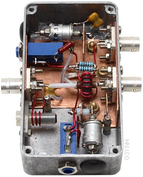
A6.5: A Self-evaluating Precision Reference Bridge.
By David W Knight
A current-transformer transmission bridge with max. φ error of ±<0.1°
and max. |Z| error of ±<0.2% over the 1.6 MHz to 30 MHz range.
|
Work files (and software required to open them): |
|
Online references: |
|
Abstract: The construction and evaluation of an accurate 50 Ω impedance-matching-reference bridge operating over the 1.6 MHz to 30 MHz range is described. The bridge is based on a 1:12 toroidal current transformer and has a nominal mid-band insertion loss of 0.06 dB. The maximum recommended continuous power throughput is 100 W. |
|
Voltage sampling is by means of
a capacitive potential divider. Two-point magnitude-vs.-frequency
tracking is achieved by adjustment of the potential-divider ratio
at the LF end of the operating range and by adjustment of an
inductance compensation coil at the HF end. LF phase compensation
is by means of an adjustable resistance in parallel with the
lower voltage-sampling arm. A wire passing through the transformer core is used for HF phase compensation. A quadrature current is injected into this auxiliary winding by means of an adjustable capacitor. Fine control of the phase of the correction signal is achieved by means of an adjustable resistance connected across the extra winding. This arrangement gives three-point phase-vs.-frequency tracking. |
 |
|
The bridge is rendered self-evaluating
by choice of orthogonal adjustments for resistance and reactance
balance, and by including provision for the associated adjustment
parameters to be measured. The theoretical basis on which frequency-dependent
deviations of the parameters from their calibration settings
can be converted into performance data is given. Both Faraday-shielded and unshielded versions of the current transformer were tried. In both cases, with the bridge maintained at constant temperature; the maximum maximum peak-to-peak phase runout was about ±0.03°; and the maximum magnitude runout was about ±0.04%. The ultimate magnitude accuracy is limited by the uncertainty in the value of the reference load resistance used during calibration. Using a 4½-digit Fluke 8060A multimeter for the resistance measurement gave a final magnitude accuracy of about ±0.13%. The results obtained constitute a two orders-of-magnitude improvement over typical Douma (CVS) transmission-bridge designs. The effect of temperature variation on phase accuracy is investigated. This issue is related to the temperature coefficient of the permeability of the transformer core. The effect is only significant at low frequencies. A compensation scheme using a Linear PTC thermistor is proposed but not tested. |
© D W Knight 2007, 2014
David Knight asserts the right to be recognised as the author of this work.
|
|
|
|
|
|