|
The ratio arms of an alternating current Wheatstone bridge consist
of two inductive windings which are bifilarly wound on the same
core and are surrounded by a shield which is connected to the
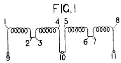
common middle point of the ratio arms. As shown in Fig.1, the
windings 1, 2 and 5, 6 are formed of a twisted pair of conductors
and are wound by starting at the ends 2, 6, so that the ends
1, 5 appear at the outside. The windings 3, 4 and 7, 8 are similarly
wound but in the reverse winding direction. The coils are connected
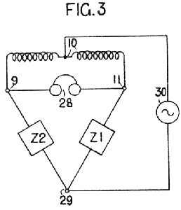
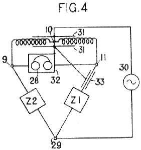
as shown in terminals 9, 10, 11 and are inserted in a Wheatstone
bridge to form the ratio arms as shown in Fig. 4. For currents
entering at point 10, the windings oppose inductivity, giving
a small impedance, while for currents passing through the coils
from the end 9 to the end 11 the windings aid inductivity and
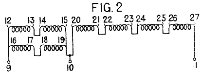
present a very high impedance. A coil for 4 to 1 ratio arms is
wound from a four-conductor strand, one arm comprising four windings
in series and the other comprising two pairs of conductors in
parallel. Similarly other ratios may be obtained. The bridge,
Fig.4, is arranged for the comparison of impedances Z1, Z2, balance
being indicated by telephones 28. The ration arms are shielded
by an electrostatic screen 31 connected to the mid-point 10.
A similar shield 32 may be provided for the telephones 28, and
if the impedance Z! to be measured is at a distance from the
bridge, the lead from terminal 11 may be provided with a shield
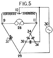
33, also connected to the mid-point 10. Fig. 5 shows the bridge
arranged for measuring the capacity between two conductors 34,
35 in the presence of a third conductor 36, which is connected
to the mid-point 10 so that the capacity between the conductors
35, 36 is bridged across the generator 30, and that between the
conductors 34, 36 is bridged between the substantially equi-potential
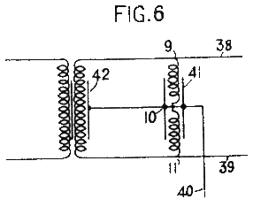
points 10, 11. As shown in Fig. 6, the coil windings 9, 10, and
10, 11 form ratio arms bridged across the conductors 38, 39 of
a side circuit in a telephone phantom group. The shield 41 of
the ratio arms and the shield of 42 of the side circuit repeating
coil are connected to the mid-point 10 from which a conductor
40 gives access to this half of the phantom circuit. |
