|
|
|
"High-fidelity" AM broadcast detector
by Robert Batey, KF7FTQ
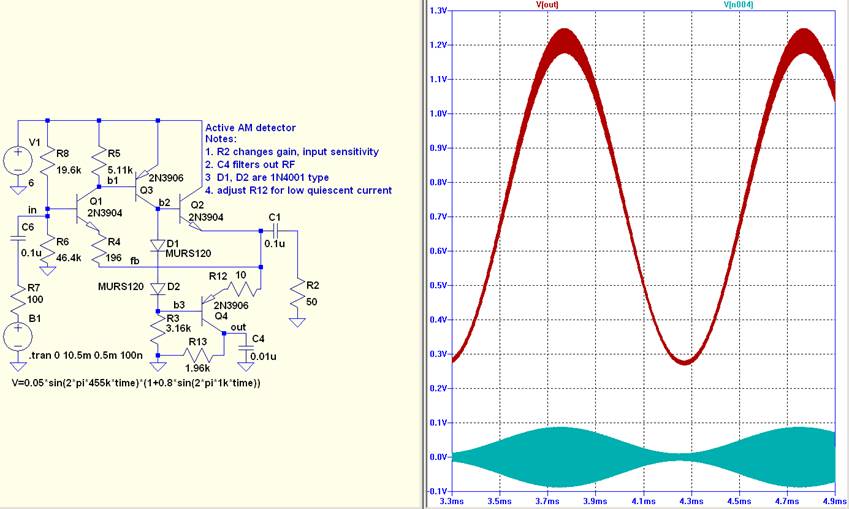
| Here is a modification to David Knight's linear detector circuit. I wanted to build a "hi-fidelity" AM receiver and needed an ultra-linear AM detector for it. Here is the circuit I came up with: |
|
Note that I eliminated the meter circuit, and removed a lot of
the bypass caps. I now have a circuit that has a finite quiescent
current at the output terminal but is extremely linear as you
can see. The input waveform is the lower trace, upper trace being
the output. My strategy is to adjust R2 so that the input signal
gives the proper signal swing. In the application I will replace
C4 with a better filtering system and 10 kHz. notch filter. This
should do nicely and is far superior to a germanium diode detector. The simulation shown is for 455 kHz, but (subject to practical confirmation) it appears that the circuit will work to well over 5 MHz. Below is the schematic of the complete detector with 10 kHz notch filter (for the American band plan). The filter gets rid of the adjacent-channel carrier heterodyne whistle, which can be bad at night when the sky-wave comes in . It can be re-tuned for the European 9 kHz channel spacing as well. One reason for using Dave Knight's method of linearizing the detector is that it fits well with a low voltage single supply. As you can see I powered my 455 kHz. detector from 6 V and it has a buffered output. I discovered "Hi-Fi AM" quite by accident too. It can rival FM to some extent and some of the venues on AM here in Idaho are not available on FM. |
|
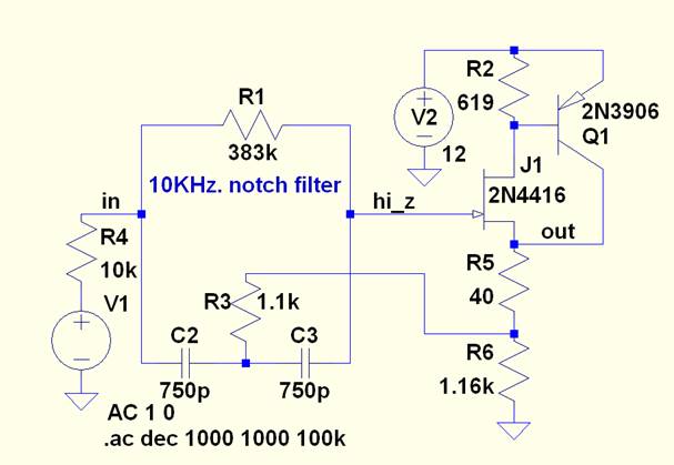
Notes on the notch filter: Here is the simple design with a FET-BJT buffer using single supply (12 V) and no op-amp. |
|
The input Z is high enough so that the detector circuit can drive
directly into the notch filter with no additional buffering.
Supply voltage for this circuit can vary between 5 V and 12 V
with no ill effects. Voltage divider R5/R6 controls the circuit
Q, R3 controls the center frequency but may interact with the
Q (second order). R5/R6 can be realized with a 1 k resistor in
series with a 200 ohm trim pot. R3 can be realized with another
1 k resistor in series with a 200 ohm trim pot connected as a
rheostat. This will allow trimming of the circuit to match the
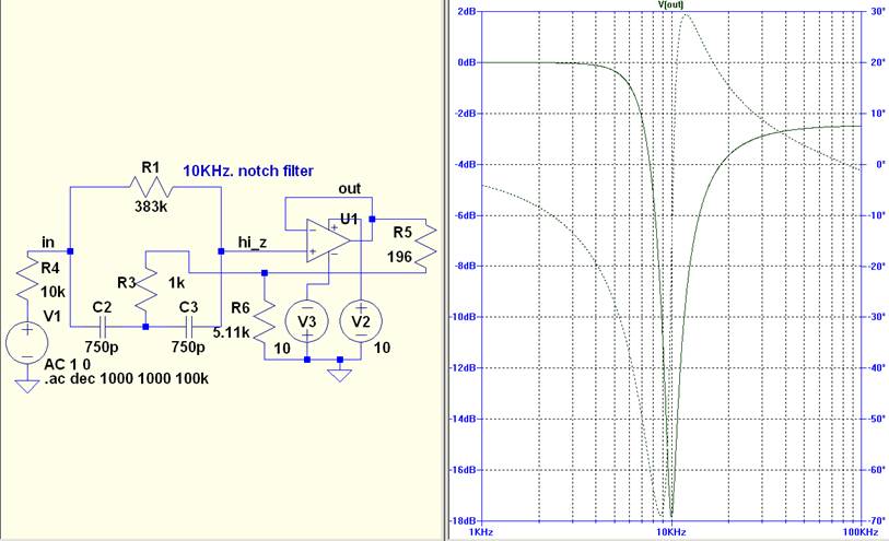
18-20 dB notch and center frequency of 10 kHz. Older design from National Semiconductor App note: One of the problems with AM broadcast reception using a relatively wide IF bandwidth is that the stations transmit full carrier and the channel spacing is only 10 kHz (in America, 9 kHz in Europe). Thus it is possible to receive a 10 kHz "whistle" when reception is good (such as at night). This high pitched noise is easy to hear for most people. The next channel is 20 kHz. away, which is out of typical adult hearing range, and the LPF in the detector attenuates it as well. Here is a good "whistle" filter for the MW band that doesn't degrade the audio frequency response. |
|
Note that it is a bridged-T design and uses an op-amp. The filter
is bootstrapped with feedback from the unity follower. It is
possible that an emitter follower could be used as well for this,
but the 383 k resistor requires a very high input impedance for
the buffer amplifier. The voltage divider formed by R5 and R6 will increase the Q as R5 is lowered and R6 is raised in value. Care must be used, however, as the notch depth is affected, and there is less notch depth as the Q increases. The idea for the filter comes from National Semiconductor Linear Brief 5. This shows a full twin-T notch filter bootstrapped to improve the Q. I found that the same technique could be used to bootstrap a bridged T circuit. Bob Batey, Eagle, Idaho, June 2009. |
Superhet Hi-Fi AM Tuner
by Robert Batey
|
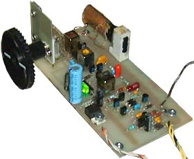
Here is a Hi-Fi AM superhet receiver using the linear detector
discussed above. The whole thing fits on a small PC board pictured
right. The linear detector is on the part of the PC board in
the foreground, and the TO220 package to the left of it is an
LM317 voltage regulator for the 6 V power rail. The front end circuit is shown below. It uses the NXP / Philips NE602 double-balanced mixer chip; or, as here, the SA612, which is a lower cost version. |
 |
|
C5 and C6 were NOT fitted in the final build. The NE602 / SA612
has differential input and output, but I wanted the option of
running single ended in case the ground would help. The filter
formed by the 21.5 ohm resistor and 10uH choke keeps feedback
from occurring through the power supply rail, which will cause
the receiver to oscillate if those components are not present.
C17 is part of that filter too. The oscillator coil was used
"inverted" from what is normal. The tap is closest
to the "hot" end of the coil, since the SA612 oscillator
doesn't need much "step-up" from the transformer. In
fact, the resistor is to reduce the drive somewhat, to keep the
oscillator amplitude from being too much. To avoid stability problems, the "loopstick" antenna should preferably be shielded from the rest of the circuit. Placing the circuit in a metal box, with the loop antenna outside is optimum. My implementation had the loop antenna attached to the PC board, which allows some feedback through the receiver of the 455 kHz. signal and hence some "tweet". The IF amplifier is shown on the complete Circuit Schematic (GIF image, click to open it in a separate browser window) and is discussed in more detail later. Note that the Toko IF transformers have an internal resonating capacitor, which is not shown on the diagrams. The detector and audio output part of the circuit is shown below. |
| Q7, Q5, Q6, and Q8 comprise the detector circuit. Q9 and Q10 form a unity gain buffer, and 3-pole active low pass filter that cuts off at 7 kHz. (12 dB down at 10 kHz.). Q9 is a BF244B N channel JFET. The IF amplifier has AGC driven by the detector output at the top of R16. |
|
- - - |
LPF DC Operating Point --- |
| V(supply): | 6 V |
| V(out): | 2.0419 V |
| V(d): | 5.35688 V |
| Ic(Q5): | -0.645428 mA |
| Id(J1): | 1.04209 mA |
|
The audio filter circuit that I designed in did not use the notch
but is an S-K (Sallen-Key) 3 pole design. It could be tweaked
a bit for the European station spacing, but is probably okay
without any design change as it is. The filter compromise reduces
noise at the expense of bandwidth. Most cheap radios have inadequate
filtering, erring on the side of too much in the case of AM tuners
(about 3 kHz. roll off) to too little in the case of cheap radios.
I erred on the side of (perhaps) too little, in order to include
more bandwidth so that the audio upper spectrum would be present
if broadcast. I'm relying on the sharper cutoff of a 3-pole Chebyshev
filter to help more with noise while allowing "flat"
(has some peaking) response to 6.6 kHz. Listening revealed that
I could get a little more by allowing 10 kHz. bandwidth, but
the noise was much more noticeable. The chosen bandwidth works
with the 9 kHz. European. channel spacing as well. Note that I used a BF244B FET in the circuit, but a 2N4416 for the simulation. The two devices have very close to the same characteristics. Also, the filter works just about as well with some standard components for C4 and C2. Here are the new values: C4 old=15 nF, new=10 nF C2 old=39 nF, new=33 nF The resulting filter response looks very much the same, but the filter gains some bandwidth. These parts are easier to get, but 5% tolerance would be advised for C2, C3, and C4. I later discovered that the JFET-BJT follower circuit works better when the drain resistor (R14 in the simulation, R18 on the full schematic) is increased to 1 k ohm. I made this change when I found that one of my circuits had more distortion than expected. The FETs have a lot of variation, and increasing the resistor value makes the circuit more tolerant over the full range of possible BF244B FET characteristics. I have to say that this tuner gives me "near FM" quality on AM. The few distractions come from static which AM is famous for, and can't be eliminated, but other than this, it sounds great. Bob Batey, Eagle, Idaho, July 2009. |
RF (or IF) Amplifier with AGC
by Robert Batey, July 2009.
|
The usual way to make a gain controllable RF amplifier is to
use a circuit based on a Gilbert Cell (as when using a 4-quadrant
multiplier to make a VCA). One chip that has a built-in Gilbert
cell is the MC1350 IF amplifier. The circuit below uses a different
technique, and is the basis of the IF amplifier used in the superhet
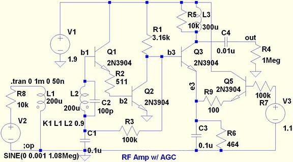
receiver described above.. A simple differential pair can be used to build an effective AGC. It's done by loading one of the devices with the LC circuit and using the other half to steer current away or towards the other device. Since Re=(1/Ie)*KT/q, varying Ie will change the gain of the stage. It's simple but gives lots of dB of gain change. |
|
In the picture above, Q3 is the gain stage, and Q5 is used to
vary the current in Q3. In the SPICE simulation I got over 40
dB of AGC action. Replacing L3, and L1/L2 with IF transformers
gave me a nice IF amplifier with plenty of gain. The loading
on the transformers preserves the Q and V3 was generated by the
ultra-linear detector circuit (averaging the output). The AGC
cuts in when V3 exceeds about 1.1 V. R9 was changed to 10 ohms,
but the circuit will probably work just as well with no resistor
at all (0 ohms). I measured the linearity at the detector, and as long as the circuit is not over-driven at Q1/Q2, the distortion is quite good. It's because all the devices are biased properly. V1 is generated by using an LED as a shunt voltage regulator. Power supply variations don't effect things much. There is enough gain in this circuit to use it directly as a TRF stage ahead of the ultra-linear detector. I used a ferrite loopstick in place of L1/L2 to do this, and coupling the output ("out" node) to the detector circuit. In the case of the superhet design, the NE602 balanced mixer stage is placed ahead of this circuit. |
TRF Receiver with Regeneration.
by Robert Batey
|
This circuit does not have an ultra-linear detector, but could
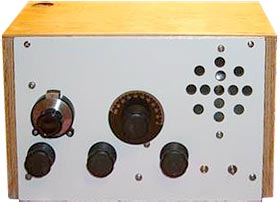
easily be adapted. When I built this receiver, I wanted an "antique"
radio to play with. This one does nicely. It looks like one,
but has modern components inside for reliability (rather than
vacuum tubes). Controls (L to R): top, bandspread tuning, main tuning; bottom, RF gain, regeneration (reaction), audio gain, phone jack (3.5mm), power switch |
 |
|
Click the link to see the full circuit schematic (GIF image, opens in
a separate window). This is a very simple design but amazingly good. It uses one CA3046 or similar transistor array, one JFET, and one LM386 audio amplifier (3 active components, 1 germanium diode). The FET is a BF244B or 2N4416 (either will work). The regen control smoothly transitions the circuit into and out of oscillatory mode. Most other designs I experimented with, had problems adjusting the regeneration. The receiver requires a small wire antenna, of about 10 feet (3m). I strung mine between curtain rod supports above my window, and placed the radio on the table next to my bed. The receiver sounds really good on MW, because it has more bandwidth (less selectivity). It needs a better audio filter though, because it has too much audio bandwidth and so lets in more noise than is necessary. |
| The circuit uses ONE simple coil, with no taps or complexities. Any RF choke from the "junkbox" can be used for a coil, because the circuit is a Q-multiplier - the gain element cancels the losses in the resonant circuit. The 5.6uH coil was a molded RF choke. For MW I used a loop stick antenna and unwound some turns from it. BUT the circuit requires a trim capacitor that may need be different for each band. (I later found that 5pF. worked for both MW and SW, from 4-12 MHz.). |
|
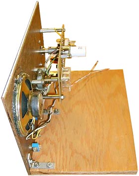
I recommend the use of plug-in coils
to change bands (simple). I mounted my coils on 3 pin DIN plugs.
I have 2 coils, one for MW and the other for 4-12 MHz. SW reception.
For "bandspread" control, I used small variable 2-25
pF cap in parallel with main tuning capacitor. Both tuning caps
have a vernier for easy tuning. The plug-in coil is visible on
the top of the PC board (the white cylinder). The receiver has a grounded gate RF amplifier, which increases sensitivity and reduces spurious radiation when the regen is is turned up too far. I had to add a 10 k pot in front of the RF stage to be able to keep the receiver from overloading on strong signals, especially MW. Resistor R3 was changed from 2.2 k to 5.11 k for lower battery current (and performance was actually better). |
 |
|
Referring again to the full circuit schematic;
notice that the 1N34A diode detector does not have a DC return
path. The detector circuit is borrowed from an article by Charles
Kitchin, N1TEV [QST, September 2000, p61-64]. Apparently, a germanium
diode can work without bias because it has a relatively low reverse
leakage resistance. I found eliminating the diode kills the circuit,
so there is a definite rectifying action. Using a silicon PN
or Schottky diode kills the circuit too, since the reverse leakage
resistance is too high. A floating detector of this type presents a high impedance across the tuned circuit. This helps to maintain the Q, although the regen cancels the losses and so the circuit can probably stand a fair amount of loading. The use of a Schottky diode, with a conventional DC return network, will improve performance at higher frequencies; although it might be an idea to tap into the coil to get a better impedance match. I found that I could get a Schottky diode to work as a high impedance detector by placing a resistor to ground from the junction of D1 and C5. 1.8 µA of bias current did the trick for a circuit running on 1.8 V, so about 3.3 MΩ should do for this circuit. If using the front end to drive the ultra-linear detector, it will probably be necessary to tap into the coil also, mainly to reduce the gain. Note that the ultra-linear circuit will probably not work, or at least not work well, at 12 MHz; although it will work up to several MHz. I actually run the receiver on 12V power rather than 9 V. The battery pack is 2-AAA cells in series with a 9 V battery. I also increased the value of the series resistor to the shunt regulator to 2 k to reduce battery current. It's R8 on the schematic. I also have a "wall wart" power supply for the radio, to save batteries. The LM386 output stage drives a speaker easily. I ended up using a 25 Ω speaker to improve battery life (instead of an 8 Ω speaker). Bob Batey, Eagle, Idaho, July 2009. |
|
Parts sources for USA. You can buy some of the parts directly from Electronix Express |
|
|
|